|
FULLY FLOATING GIMBAL HEAD
ABOUT - CONTACTS - FOUNDATION - HOME - A-Z INDEX
BRICKWORK - CARRIAGE - DRAINAGE - FACILITIES - FILTRATION - GLASS & PAINT - GANTRY - GIMBALS - HATCHES HYDRODYNAMICS HISTORY - INSTRUMENTS - LABORATORY - LAMINATING - LOGISTICS - OUR TEST TANK - PROOFING - REVIEWS - SCREED SEALING - SEAVAX TEST VIDEOS - SLUICE GATE - SLUICE MOTOR - SOLAR BATTERIES - WAVE MAKING - WINCH - WIND MACHINE - MOUNTINGS
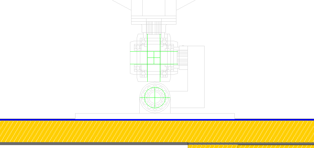
GIMBAL MOUNTINGS - Three wide spaced double ball-bearing races work together to give the boat Yaw, Roll and Pitch movements. A sliding mast provides vertical movement to allow for Heave. In the perfect world we could allow for Sway and Surge, but will instead measure the sideways forces with strain gauges and heave velocity also from pressure sensors. We will though engineer in the movement to allow for later development. Our gimbal is a custom built design. This was the draft design drawing before ordering parts. Copyright © drawings January 12 2018. All rights reserved. You will need the permission of the Cleaner Ocean Foundation to reproduce these diagrams except for educational use or private research.
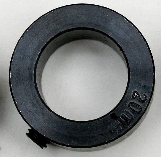
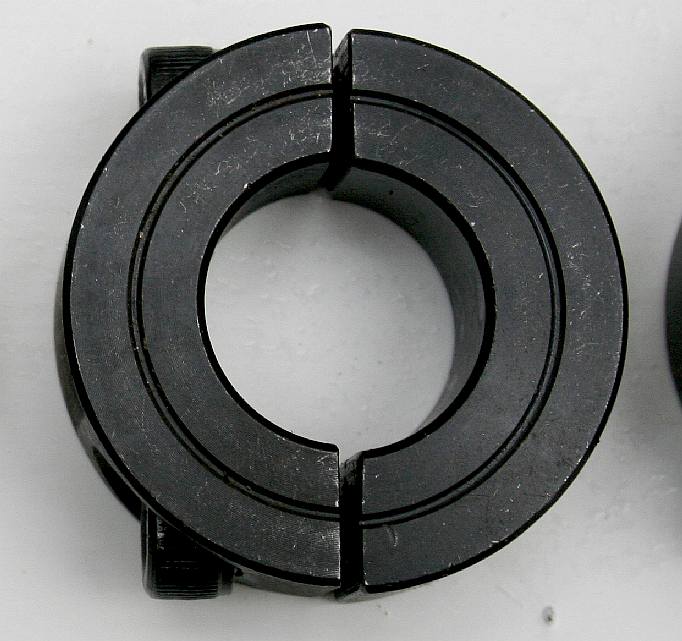
HIGH TENSILE COLLARS - Having elected to go all out for 20mm stainless pins, we needed three sets of high strength steel locking collars for the the gimbal head to prevent the pins/shafts from sliding out under heavy loads. We did not make these ourselves where our new lathe has not yet been delivered. Fortunately, there are a number of engineering firms in the UK that cater for such items and delivery is rapid. We used two types of collar, one a single piece ring with grub screws and the other a two-piece with allen-key bolts. Copyright © photographs February 7 2018. All rights reserved. You will need the permission of the Cleaner Ocean Foundation to reproduce these diagrams except for educational use or private research.
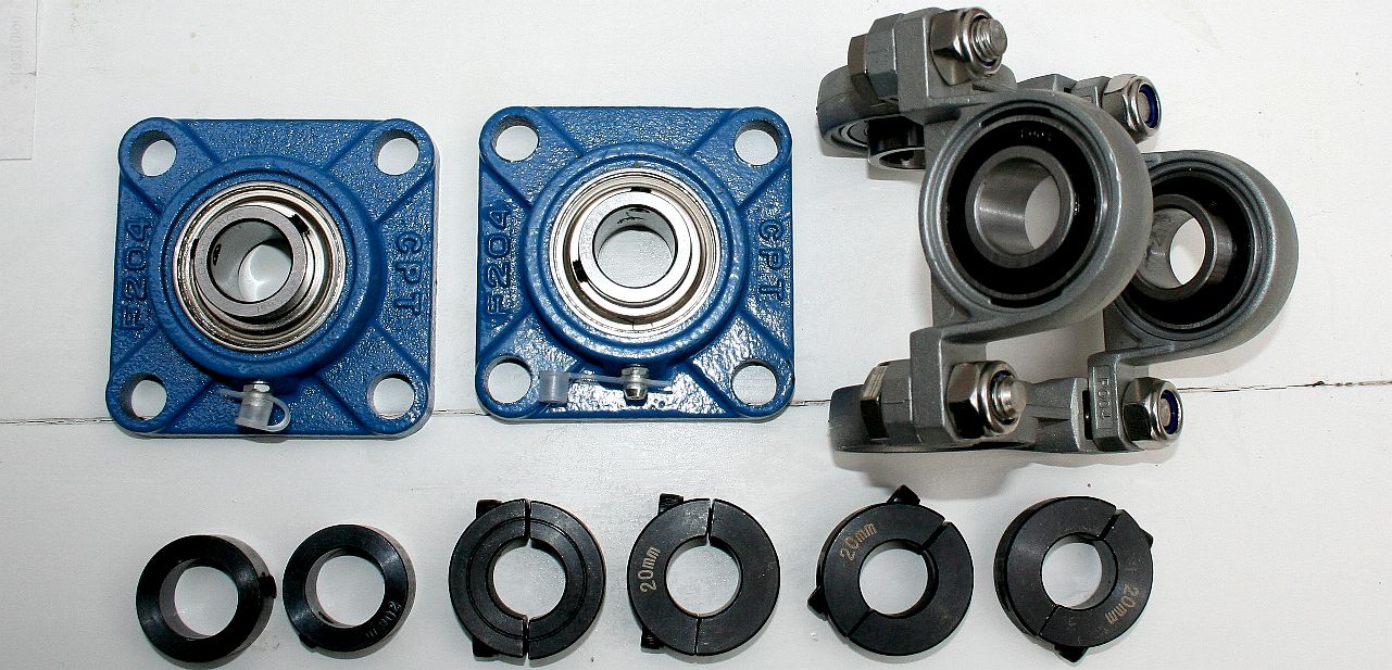
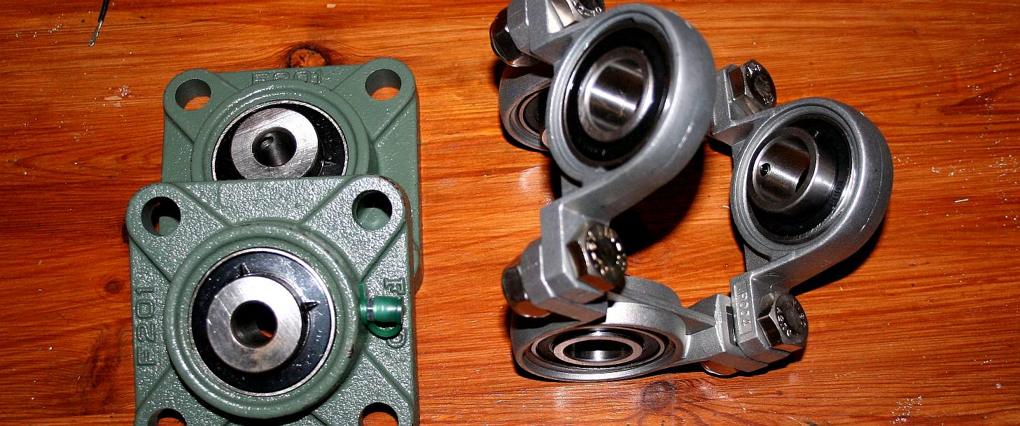
PARTS CHECK LIST - We love it when all the parts are ready to be fitted. Don't forget to work with clean hands in a dirt free environment when assembling any engineering piece. Copyright © photographs February 7 2018. All rights reserved. You will need the permission of the Cleaner Ocean Foundation to reproduce these diagrams except for educational use or private research.
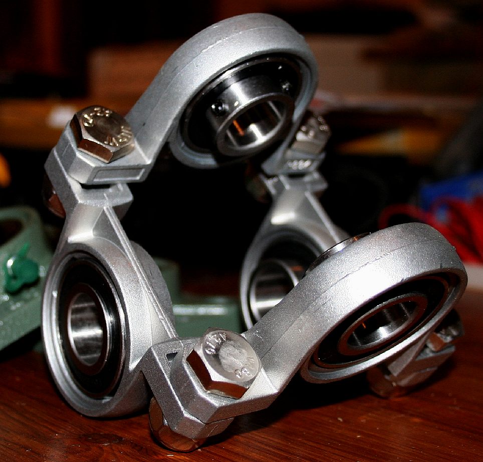
SWIVEL ASSEMBLY - With the stainless steel pins cut and ground, we test fitted the collars, aligning the pillow bearings for the first time and proving to be a bit stiff to get them in-line. We needed to resort to the largest vice in the workshop - being careful not to damage the assembly. Copyright © photographs February 7 2018. All rights reserved. You will need the permission of the Cleaner Ocean Foundation to reproduce these diagrams except for educational use or private research.
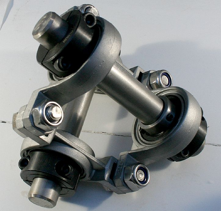
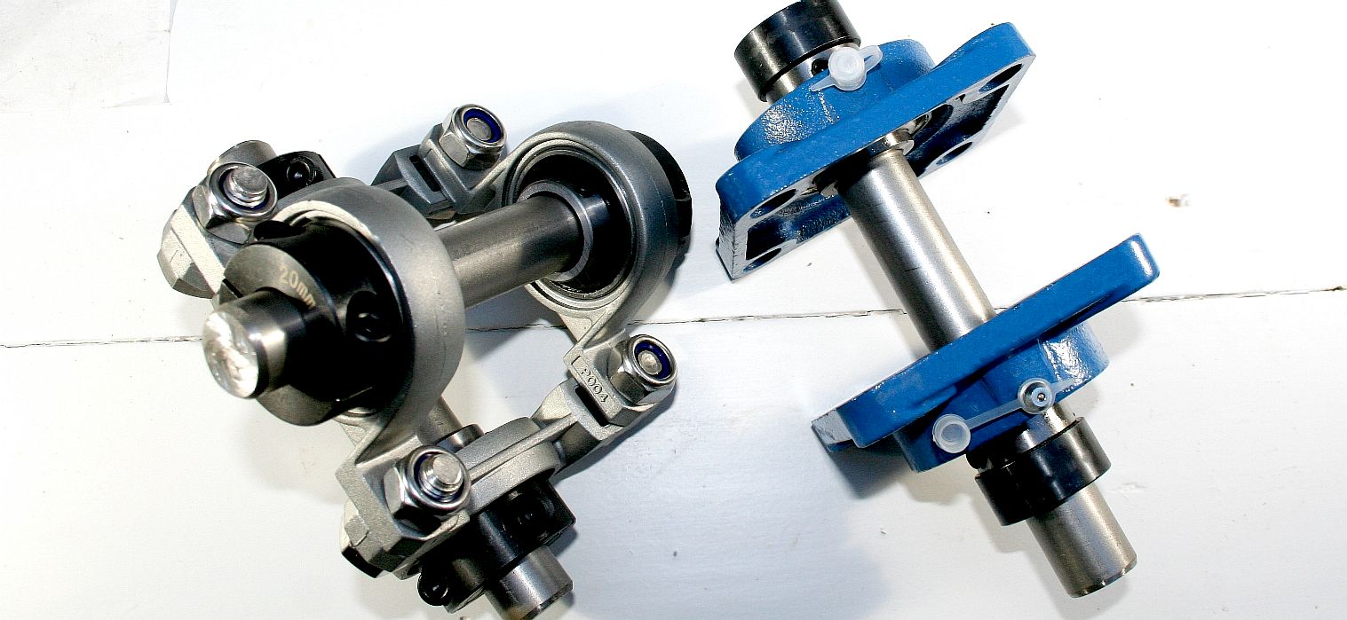
THREE AXIS BEARING SET - Here you can see the stainless steel shafts fitted on all three bearing sets with the collars lightly nipped up. The next step is to fabricate the steel 'T' sleeves from 30mm tubing and weld the component tubes together such that they are a perfect fit in the space in between the bearings. It means taking these assemblies apart and inserting the 'T' sections with plenty of waterproof grease. Copyright © photographs February 7 2018. All rights reserved. You will need the permission of the Cleaner Ocean Foundation to reproduce these diagrams except for educational use or private research.
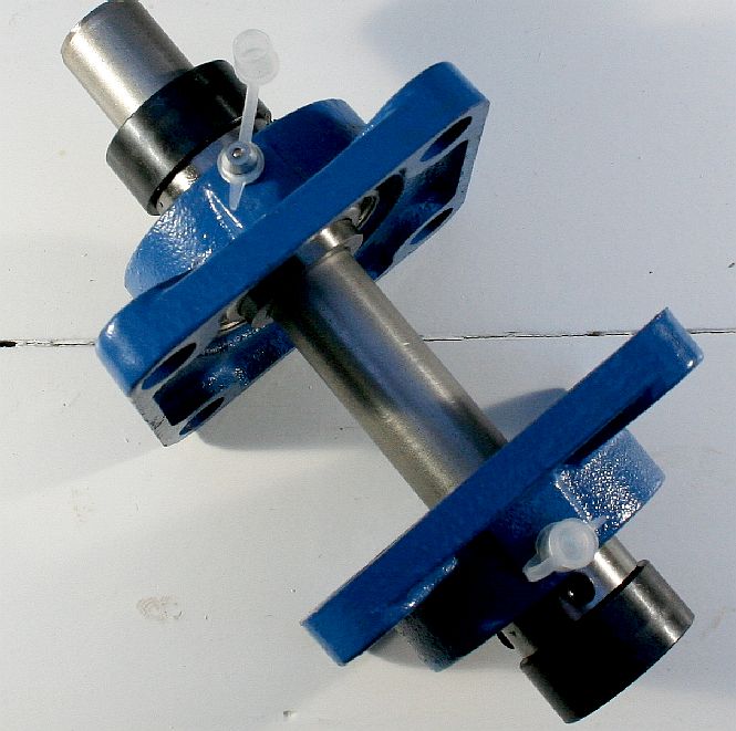
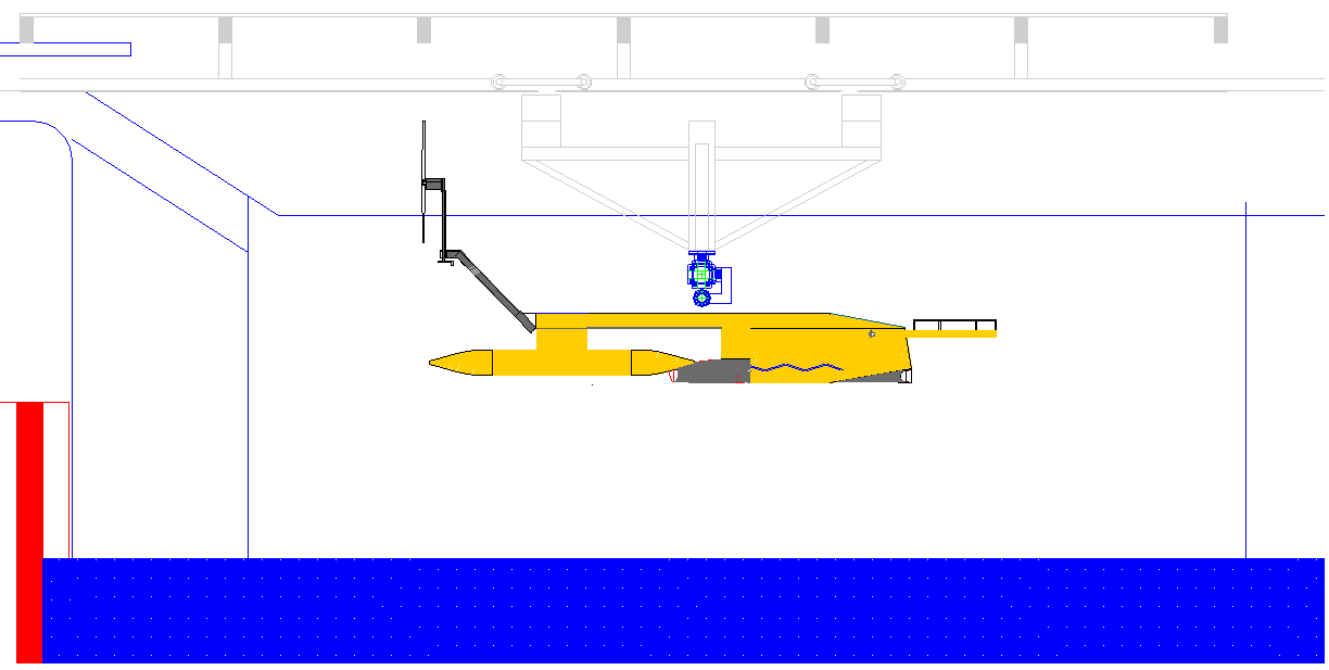
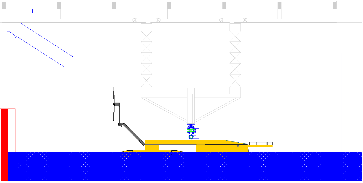
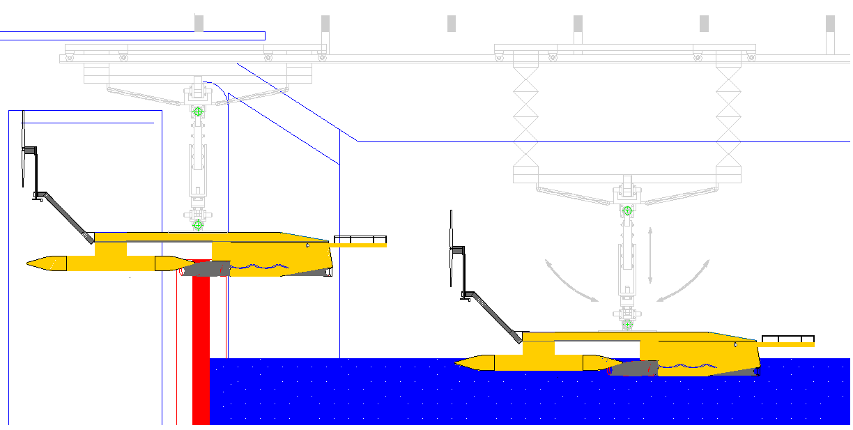
DOUBLE GIMBAL MAST - By adding a second gimbal at the carriage high end - and a linear roller bearing with the mast divided into inner and outer sections - we achieve a fully floating mounting for the model boats and ships being tested. The SeaVax concept model is shown in these diagrams. We will arrange to be able to lock any combination of the movements during trials. Copyright © photographs February 17 2018. All rights reserved. You will need the permission of the Cleaner Ocean Foundation to reproduce these diagrams except for educational use or private research.
A FULLY FLOATING HEAD
Mounting a test model such as to be fully floating is not as easy as it first appears. Not if we want to measure a whole range of forces in simulated rough weather conditions - and allow the boat to steer remotely into different weather conditions - rather than simply drag the hull. If we just want to measure hull drag that is relatively easy. We need to know the speed of the hull through the water, against the total resistance to movement at any given speed. If the water is calm, the drag should be constant with respect to any given speed.
Unfortunately, it does not stop there because a hull on the high seas is subject to forces from all directions and smaller ships rock as they negotiate waves, effectively climbing a hill then skiing down a slope and crashing into the hollow - if the wave if that large. In high winds and rough seas a vessel like SeaVax may find it difficult to maintain steerage. One very good reason to want to test that aspect with the boat operating under its own power.
A model behaves in the same way as its full size counterpart and that is lucky for us because we can work smaller at lower cost to testing everything out with a big ship offshore. We can work anywhere we have a controlled body of water, so long as our water basin is large enough to accommodate the model we intend testing.
HOW DIFFICULT IS IT TO MEASURE WHAT IS GOING ON?
We need to allow the model to move in relation to the dynamics of the waves that we will be generating to replicate the movements that the full size boat will experience.
To make this possible we use a Gimbal mount similar to those you may have seen for cameras. Gimbals were normally used to keep nautical instruments horizontal at sea, or even galley stoves, years before cameras were invented.
A gimbal is a pivoted support that allows the rotation of an object about a single axis. A set of three gimbals, one mounted on the other with orthogonal pivot axes, may be used to allow an object mounted on the innermost gimbal to remain independent of the rotation of its support. For example, on a ship, the gyroscopes, shipboard compasses, stoves, and even drink holders typically use gimbals to keep the object inside the swivel upright with respect to the horizon despite the ship's pitching and rolling. What a gimbal cannot cope with is Heave, Sway and Surge.
GIMBAL LOCK UP
We need to be able to lock any of the three rotational axes to conduct specific roll and pitch experiments, just the same as free movement allows us to steer the boat under its own power to see how effective the rudders are.
FILMS CAMERAS
Handheld 3-axis gimbals are used in stabilization systems designed to give the camera operator the independence of handheld shooting without camera vibration or shake. Powered by three brushless motors, the gimbals have the ability to keep the camera level on all axes as the camera operator moves the camera. An inertial measurement unit (IMU) responds to movement and utilizes its three separate motors to stabilize the camera.
We do not want to keep our test models level, we want them to move like the real thing and be able to measure the forces on the hull in conditions that as accurately as possible simulate the open ocean.
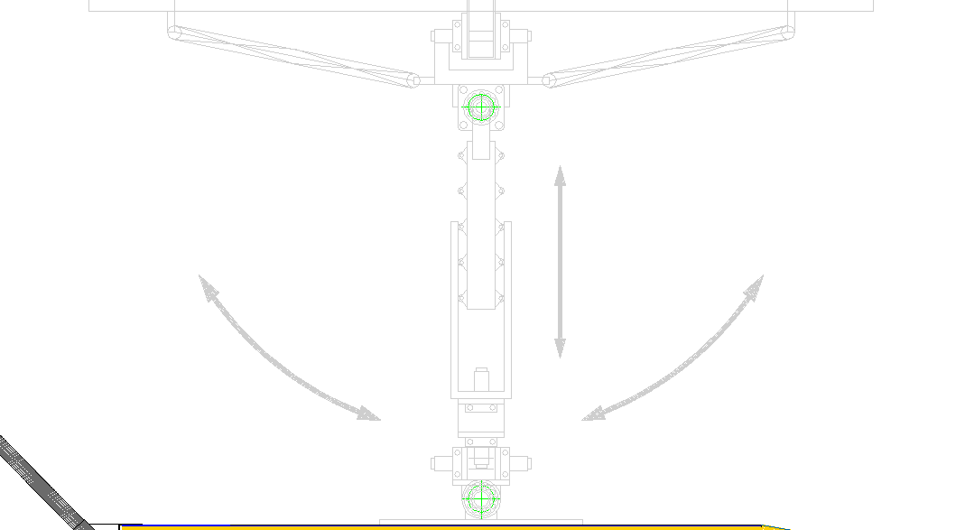
THREE AXIS GIMBAL - The mounting joint or neck is fixed to the hull via a large flat plate to spread the loads such as not to damage the model. With the other freedoms, we can measure roll, pitch and yaw, combined with heave and sway. In circulation mode, we can also measure hull drag against wave conditions. We need to be able to lock any axis of movement to be able to conduct hull test such as in high wind conditions.
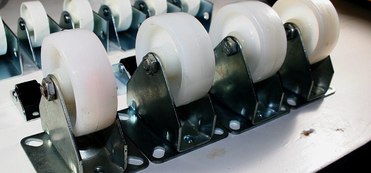
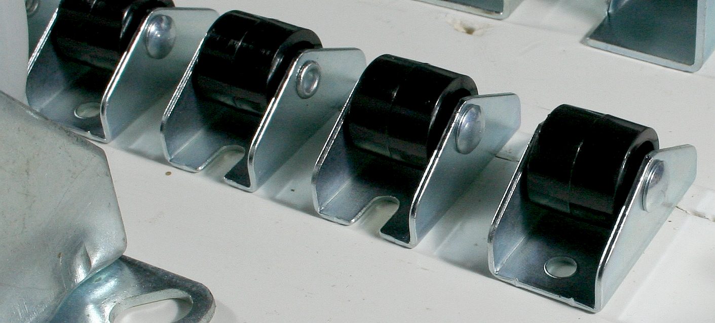
CARRIAGE ROLLERS - Eight of these 50mm heavy duty nylon wheels allow the carriage to glide across the stainless steel gantry rails. They work in conjunction with another four guide wheels for a smooth action. Copyright © photographs February 14 2018. All rights reserved. You will need the permission of the Cleaner Ocean Foundation to reproduce these pictures except for educational use or private research.
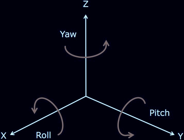
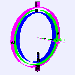
THE SIX DEGREES OF FREEDOM
A vessel on water is free to rotate in three dimensions: pitch, bows up or down about an axis running from sponson to sponson in a catamaran; yaw, bows left or right about an axis running up and down; and roll, rotation about an axis running from the bow to the stern of the vessel.
The axes are alternatively designated as lateral, vertical, and longitudinal. These axes move with the vehicle and rotate relative to the Earth along with the vessel.
These rotations are produced by torques (or moments) about the principal axes. On a boat, these movements are reactions to (unintentionally produced) wave and wind forces, which vary the distribution of the net hydrodynamic and aerodynamic forces about the vessel's center of mass.
There are other forces on the hull of a ship such as when a wave slams into the hull from the side (sway), or when the waves lift the hull up and then down (heave). Surge is where water drag or currents either slow or accelerate a hull backwards or forwards.
In an aircraft elevators (moving flaps on the horizontal tail) produce pitch, a rudder on the vertical tail produces yaw, and ailerons (flaps on the wings that move in opposing directions) produce roll. These are intentional movements.
On a spacecraft, the moments are usually produced by a reaction control system consisting of small rocket thrusters used to apply asymmetrical thrust on the vehicle.
ROTATION MOTIONS
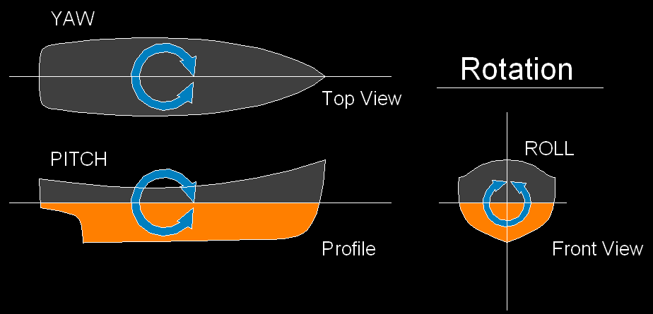
There are three special axes in any ship, called vertical, lateral and longitudinal axes. The movements around them are known as roll, pitch and yaw.
Pitch - is the up/down rotation of a vessel about its lateral/Y (side-to-side or port-starboard) axis. An offset or deviation from normal on this axis is referred to as 'trim' or 'out of trim'.
Roll - is the tilting rotation of a vessel about its longitudinal/X (front-back or bow-stern) axis. An offset or deviation from normal on this axis is referred to as list or heel. Heel refers to an offset that is intentional or expected, as caused by wind pressure on sails, turning, or other crew actions. List normally refers to an unintentional or unexpected offset, as caused by flooding, battle damage, shifting cargo, etc. The rolling motion towards a steady state (or list) angle due to the ship's own weight distribution is referred in marine engineering as heel.
Yaw - is the turning rotation of a vessel about its vertical/Z axis. An offset or deviation from normal on this axis is referred to as deviation or set.
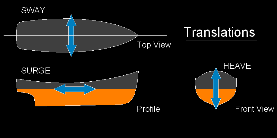
LINEAR MOTIONS
Heave - is the linear vertical (up/down) motion; excessive downward heave can swamp a ship.
Sway - is the linear lateral (side-to-side or port-starboard) motion. This motion is generated directly either by the water and wind currents exerting forces against the hull or by the ship's own propulsion; or indirectly by the inertia of the ship while turning. This movement can be compared to the vessel's drift from its course.
Surge - is the linear longitudinal (front/back or bow/stern) motion imparted by maritime conditions.
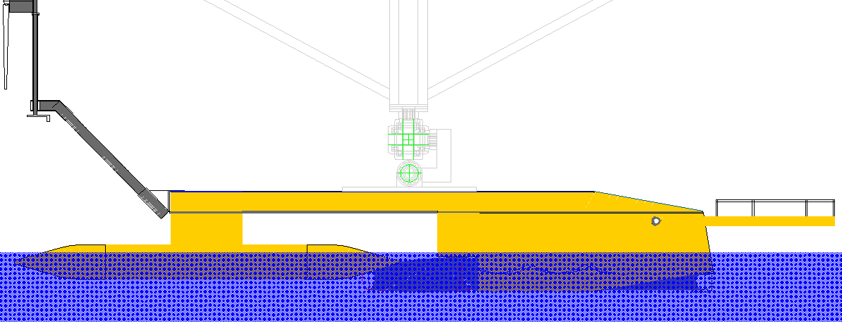
LOWERING - Seen here in the raised position and central to the tank, we can now lower the test model into the water. The carriage allows us to take the model left or right for servicing or dismounting, without having to empty the water, or wade in - although it is shallow enough for that. Copyright © drawings January 12 2018. All rights reserved. You will need the permission of the Cleaner Ocean Foundation to reproduce these diagrams except for educational use or private research.
LIFTING - Seen here fully lowered into the water, we can lift the hull back up (crane) to the raised position using a powered winch. In the lowered position we can run our tank tests. Copyright © drawings January 12 2018. All rights reserved. You will need the permission of the Cleaner Ocean Foundation to reproduce these diagrams except for educational use or private research.
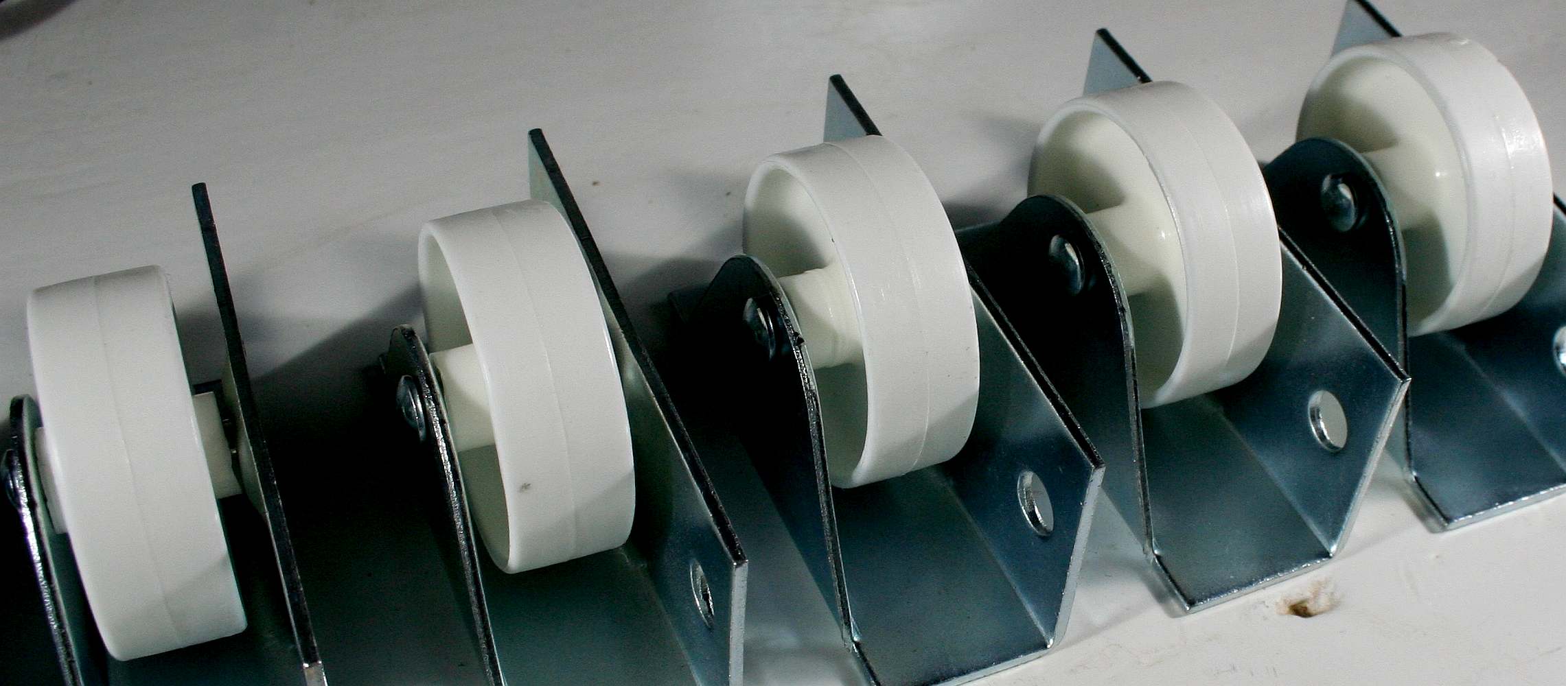
MAST ROLLERS - Thirty-two of these 15mm nylon rollers fitted vertically onto a sliding steel upright allow test models to rise and fall with the waves. Coupled with the gimbal head it is possible to attain an almost totally free floating boat, except for heave and sway - two movements that are both measured with load cells - that we are presently working on also making free-floating - provided that the whole assembly is not compromised in the process. Copyright © photographs February 14 2018. All rights reserved. You will need the permission of the Cleaner Ocean Foundation to reproduce these pictures except for educational use or private research.
CARRIAGE ROLLERS - Four of these 35mm medium duty nylon wheels guide the carriage assembly, stopping it from twisting or other sideways movements - as it rests in the overhead gantry rails. They work with eight heavy duty rollers to provide smooth transit from outside the tank - across the water - to the other side. Copyright © photographs February 14 2018. All rights reserved. You will need the permission of the Cleaner Ocean Foundation to reproduce these pictures except for educational use or private research.
LOADING - The mast can be raised to clear the sluice gate for loading, then carried out into the water tank and lowered into the water. This is the fully floating head version with 6-axis movement. We can measure roll, pitch, yaw, heave, sway and surge with this setup. Copyright © drawings February 17 2018. All rights reserved. You will need the permission of the Cleaner Ocean Foundation to reproduce these diagrams except for educational use or private research.
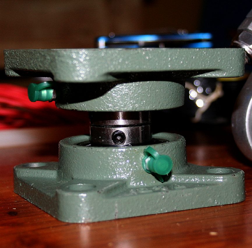
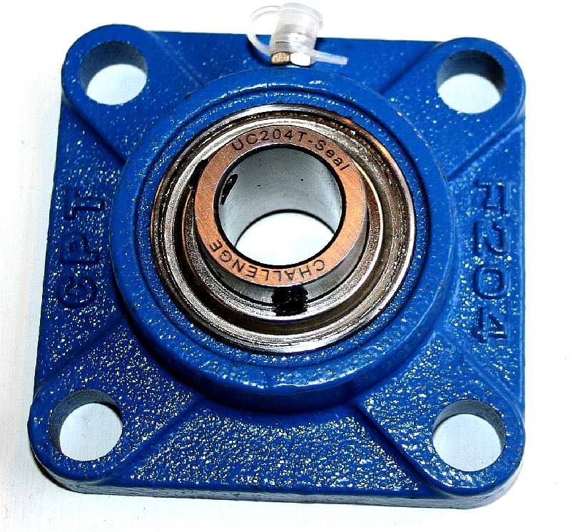
HEAVY DUTY BEARINGS - Translating the design drawings into 3D reality is the fun part. Some of these bearings (6) were used to make the three axis gimbal head. The head has to be strong enough to cope with at least a 50kg (112lb) model when it is subject to rough water conditions. We have allowed for 250kg loadings as being a suitable safety margin using 20mm shafts for the axis - hence - the blue and silver bearings, rather than the green (15mm) that would have done the job but we wanted the extra safety margin and universal shafts - we all make mistakes. Copyright © photographs January 23 2018. All rights reserved. You will need the permission of the Cleaner Ocean Foundation to reproduce these diagrams except for educational use or private research.
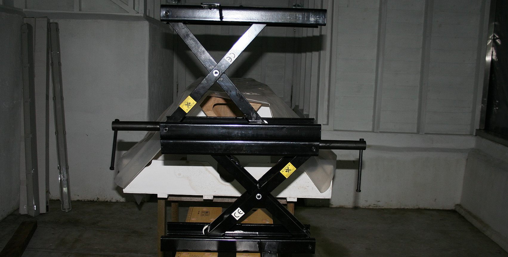
HEAVY DUTY JACKS RAISED - The difficulty we had was sourcing a lifting and lowering mechanism that came within our budget. We decided on using a scissor jack system with a 500kg load carrying capacity as a static measurement, but halved to 250kg for our dynamic tests + a hefty safety margin. We had to use two jacks in series to achieve around 600mm of lift. Here you can see the jacks compressed up, or in the raised position. We have to modify these units by welding them together and replacing the scissor-screw mechanism with a heavier electric duty winch system. Copyright © photographs January 23 2018. All rights reserved. You will need the permission of the Cleaner Ocean Foundation to reproduce these diagrams except for educational use or private research.
LOWERED - In this picture you can see the jacks in the lowered position - when used as jacks that are of course in the raised position. It's role reversal in our application. We are using a 4,000lb electric winch with remote control. All of the machinery in this test tank will be 12 volts, except for the wind generating fans and LED lighting. Copyright © photographs January 23 2018. All rights reserved. You will need the permission of the Cleaner Ocean Foundation to reproduce these diagrams except for educational use or private research.
LINKS & REFERENCE
https://www.nrc-cnrc.gc.ca/eng/solutions/facilities/marine_performance/towing_tank.html
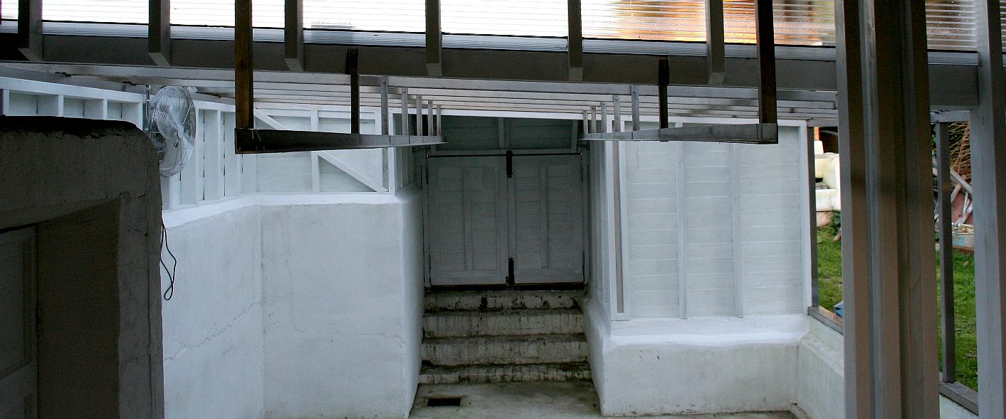
OVERHEAD GANTY - The water test-tank looked like this in October of 2017. The tank area is due for a couple of coats of epoxy paint before it can be used for experiments in 2018. Copyright © photograph. All rights reserved. You will need the permission of the Cleaner Ocean Foundation to reproduce this picture except for educational use or private research.
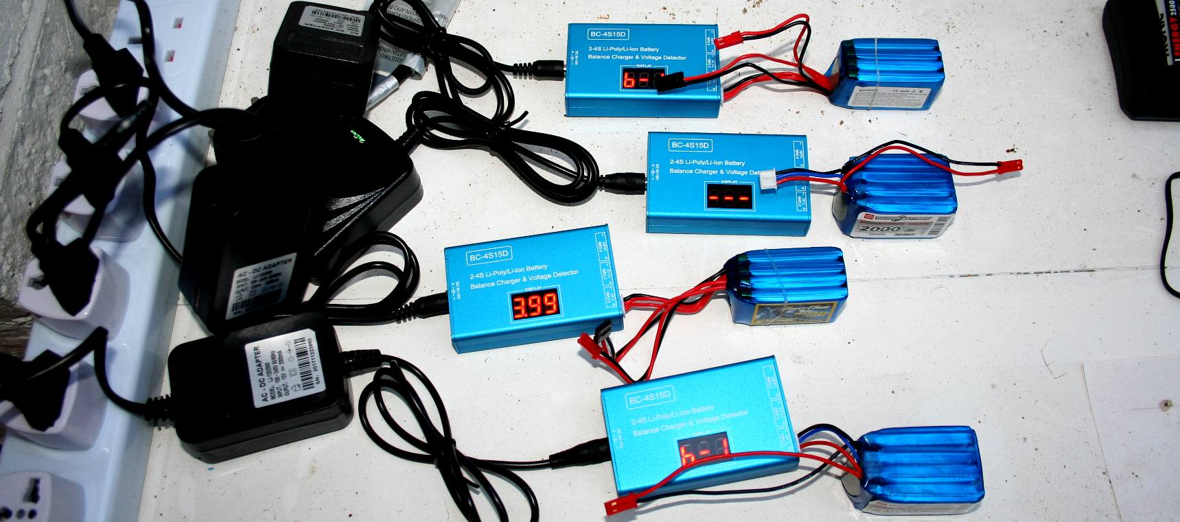
CHARGING STATION - Back in the robot lab they are working out the wiring and safety temperature monitoring to be able to charge 12 lithium batteries of different voltages and capacities all at the same time. This is so that AmphiMax and SeaVax experiments may be conducted in tandem, such as when simulating an ocean launch in the test tank. Here you can see a test charge of four small batteries that power servos and radio control gear. We use much larger packs of 14 (4s) and 24 volts (7s) and 5 amp/hour capacities to run the tracks on AmphiMax and the pumps on SeaVax. The temporary layout will be converted to a fixed arrangement once we are sure that we can charge our packs in good time to allow extended experimenting time. Copyright © photographs January 23 2018. All rights reserved. You will need the permission of the Cleaner Ocean Foundation to reproduce these diagrams except for educational use or private research.
BRICKWORK - CARRIAGE - DRAINAGE - FACILITIES - FILTRATION - GLASS & PAINT - GANTRY - GIMBALS - HATCHES HYDRODYNAMICS HISTORY - INSTRUMENTS - LABORATORY - LAMINATING - LOGISTICS - OUR TEST TANK - PROOFING - REVIEWS - SCREED SEALING - SEAVAX TEST VIDEOS - SLUICE GATE - SLUICE MOTOR - SOLAR BATTERIES - WAVE MAKING - WINCH - WIND MACHINE - MOUNTINGS
This website is provided on a free basis as a public information service. Copyright © Cleaner Oceans Foundation Ltd (COFL) (Company No: 4674774) 2018. Solar Studios, BN271RF, United Kingdom. COFL is a charity without share capital. The names Amphimax™ RiverVax™ and SeaVax™ are trademarks.
|